Lab 3
Objectives
- Make a robot that can start on a 660Hz tone
- Navigate a small test maze autonomously
- Send the maze information it discovers wirelessly to a base station
- Display maze information on a screen for debugging
Overview
This lab integrates systems that we had thoroughly developed and explained in previous labs and milestones. Below, we document the new content for this lab, RF communication between Arduinos using the transceivers provided, and the underlying software. Refer to our main page to find information about subjects like line following, collision avoidance, wall following, and 660 Hz audio signal detection.
Data structure
Because the Arduino has a very limited memory (~2KB), we decided to store all the grid’s information in a 2D byte array, where the first and second indices represent the column and row respectively, and the value determines the walls we have observed. We use the following convention, for a block in the grid array, the least significant bit represents if the eastern wall is there, the 2nd bit represents the northern wall, 3rd bit western wall, and 4th bit western wall. We have 4 bits unused, that we might utilize later on for treasure information. Also orientation can be 1 if we are facing east, 2 if we are facing north, 4 if we are facing west, and 8 if we are facing south. And this is done so we can easily multiply the boolean output of the front and right sensors by the orientation and embed it in the grid information byte (of course, shifting (or taking the remainder) is needed when the multipication output is greater than 15) so we can have only one line to compute the new block information.
grid[row][col] |= frontSensor * orientation | rightSensor * orientation * 8 | frontSensor * orientation >> 16 | rightSensor * orientation * 8 >> 16;
To transmit the data, we embed the column, row, and information byte (each of these is one byte) into a long (again, one byte of the long remains unused) and transmit it to the radio. We do the embedding by adding (or using bitwise-OR) and then shift it by the desired amount to fit everything.
Although as of now, our navigation algorithm (right wall following) doesn’t require the robots to have a copy of the grid, we keep it stored on board just in case we decided to implement Depth First Search or another algorithm for navigation.
RF communication and maze mapping simulation
For this lab, we were provided 2 Nordic nRF24L01+ transceivers (with breakout boards for easier mounting on the Arduinos), and 1 extra Arduino Uno. WATCH OUT for these RF modules!!! They broke very often and very easily. We didn’t have any issues with it, but several teams did.
These radios were connected to digital pins 9 to 13, and powered with 3.3V. We had to download the RF24 Arduino Library and were given a basic sketch as a guide to build our communication protocol.
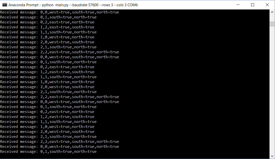
After deciding on the data structure, as discussed in the previous section, we ran a small simulation of the maze navigation to test communication between the Arduinos. Find below a video demonstration and a picture of the command prompt showing the position and walls detected during the simulation:
Partial integration
For this part, we started integrating the code for RF communication with the actual systems of the robot. For space concerns, we will not show the code for this part, as it is very similar to that in the next section, Final Integration. In this part, the robot traverses the maze using line following, wall detection, and transmits this information to the base station, which displays it in the GUI.
For this part, the base station was programmed as follows:
#include <SPI.h>
#include "nRF24L01.h"
#include "RF24.h"
#include "printf.h"
#include "Math.h"

//
// Hardware configuration
//

// Set up nRF24L01 radio on SPI bus plus pins 9 & 10

RF24 radio(9,10);
// Radio pipe addresses for the 2 nodes to communicate.
const uint64_t pipes[2] = { 0x0000000026LL, 0x0000000027LL };
//
// Role management
//
// Set up role.  This sketch uses the same software for all the nodes
// in this system.  Doing so greatly simplifies testing.
//
// The various roles supported by this sketch
typedef enum { role_ping_out = 1, role_pong_back } role_e;
// The debug-friendly names of those roles
const char* role_friendly_name[] = { "invalid", "Ping out", "Pong back"};
// The role of the current running sketch
role_e role = role_pong_back;

int rows = 2; //change grid size depending on maze
int cols = 3;
byte grid[3][2];

void setup() {
//
  // Print preamble
  //

  Serial.begin(57600);
  printf_begin();

  //
  // Setup and configure rf radio
  //

  radio.begin();

  // optionally, increase the delay between retries & # of retries
  radio.setRetries(15,15);
  radio.setAutoAck(true);
  // set the channel
  radio.setChannel(0x50);
  // set the power
  // RF24_PA_MIN=-18dBm, RF24_PA_LOW=-12dBm, RF24_PA_MED=-6dBM, and RF24_PA_HIGH=0dBm.
  radio.setPALevel(RF24_PA_MIN);
  //RF24_250KBPS for 250kbs, RF24_1MBPS for 1Mbps, or RF24_2MBPS for 2Mbps
  radio.setDataRate(RF24_250KBPS);

  // optionally, reduce the payload size.  seems to
  // improve reliability
  //radio.setPayloadSize(8);

  //
  // Open pipes to other nodes for communication
  //

  // This simple sketch opens two pipes for these two nodes to communicate
  // back and forth.
  // Open 'our' pipe for writing
  // Open the 'other' pipe for reading, in position #1 (we can have up to 5 pipes open for reading)

  if ( role == role_ping_out )
  {
    radio.openWritingPipe(pipes[0]);
    radio.openReadingPipe(1,pipes[1]);
  }
  else
  {
    radio.openWritingPipe(pipes[1]);
    radio.openReadingPipe(1,pipes[0]);
  }

  //
  // Start listening
  //

  radio.startListening();

  //
  // Dump the configuration of the rf unit for debugging
  //

  radio.printDetails();
}

void loop() {
  if ( radio.available() )
    {
      // Dump the payloads until we've gotten everything
      unsigned long got_time;
      bool done = false;
      while (!done)
      {
        // Fetch the payload, and see if this was the last one.
        done = radio.read( &got_time, sizeof(unsigned long) );

        // Spew it
        //("Got payload %lu...",got_time);

        parse_message(got_time);
        // Delay just a little bit to let the other unit
        // make the transition to receiver
      }
  delayMicroseconds(10);
}

void parse_message(unsigned long msg){
  byte x = (msg >> 3*8);
  byte y = (msg >> 2*8);
  byte info = (msg >> 1*8);
  grid[x][y] = info;
  print_toGUI(x, y, info);
}

void print_toGUI(byte x, byte y, byte info){
  bool east = info & 1;
  bool north = (info >> 1) & 1;
  bool west = (info >> 2) & 1;
  bool south = (info >> 3) & 1;

 /* Serial.print(x); Serial.print(","); Serial.print(y);
  Serial.print(",east="); Serial.print(east? "true" : "false");
  Serial.print(",north="); Serial.print(north? "true" : "false");
  Serial.print(",south="); Serial.print(south? "true" : "false");
  Serial.print(",west="); Serial.println(west? "true" : "false");
*/
  Serial.print(y); Serial.print(","); Serial.print(x);
  if(east) Serial.print(",east=true");
  if(west) Serial.print(",west=true");
  if(south) Serial.print(",south=true");
  if(north) Serial.print(",north=true");
  Serial.println();
}
Final Integration
To conclude the lab, we connected all systems to test the overall performance of the robot. Keep in mind we are using whistle detection (660Hz sound), maze navigation (line/wall following), robot detection (6.08kHz IR signal), decoy avoidance (18kHz IR signal), and data transmission with a base station that displays the detected walls on the GUI given. Also notice in the background the soundtrack of Mission Impossible, which covers a wide range of frequencies, introducing noise to the environment to test the robustness of our audio filtering.
Video
Code
#include <Servo.h>
#include "arduinoFFT.h"
#include <SPI.h>
#include "nRF24L01.h"
#include "RF24.h"
#include "printf.h"

RF24 radio(9, 10);
const uint64_t pipes[2] = { 0x0000000026LL, 0x0000000027LL };
typedef enum { robot = 1, base_station } role_e;
const char* role_friendly_name[] = { "invalid", "Ping out", "Pong back"};
role_e role = robot;


int rows = 2; //change grid size depending on maze
int cols = 3;
byte grid[3][2];


byte orientation = 1; // right = 1, up = 2, left = 4, down = 8
byte right = 1;
byte up = 2;
byte left = 4;
byte down = 8;

byte posX = -1; //to take into account that we will detect corner right when we start
byte posY = rows - 1;


arduinoFFT FFT = arduinoFFT();
#define CHANNEL A0
const uint16_t samples = 128; //This value MUST ALWAYS be a power of 2
const double samplingFrequency = 20000; //Hz, must be less than 10000 due to ADC

unsigned int sampling_period_us;
unsigned long microseconds;

#include <Adafruit_NeoPixel.h>
#ifdef __AVR__
#include <avr/power.h>
#endif

#define PIN 7
Adafruit_NeoPixel strip = Adafruit_NeoPixel(10, PIN, NEO_GRB + NEO_KHZ800);

#define SCL_INDEX 0x00
#define SCL_TIME 0x01
#define SCL_FREQUENCY 0x02
#define SCL_PLOT 0x03

#ifndef cbi
#define cbi(sfr, bit) (_SFR_BYTE(sfr) &= ~_BV(bit))
#endif
#ifndef sbi
#define sbi(sfr, bit) (_SFR_BYTE(sfr) |= _BV(bit))
#endif

double vReal[samples];
double vImag[samples];

int line_sens_pin[3] = {2, 3, 4};
long line_sens_data_time[3] = {0, 0, 0};
bool line_sens_data_digi[3] = {0, 0, 0};

#define STRAIGHT 0
#define RIGHT 1
#define LEFT  -1

int threshold = 250;
int counter = 0;
long corner_debounce = -1000;

int turn_delay = 750;

bool front_wall;
bool right_wall;

int front_wall_pin = A3;
int right_wall_pin = A5;
int wall_threshold = 175;

bool enabled = true;
Servo leftServo;
Servo rightServo;
int leftServo_pin = 6;
int rightServo_pin = 5;

long info = 0;
bool mazeUpdated = true;


void setup() {
  sampling_period_us = round(1000000 * (1.0 / samplingFrequency));
  sbi(ADCSRA, ADPS2) ;
  cbi(ADCSRA, ADPS1) ;
  cbi(ADCSRA, ADPS0) ;

  Serial.begin(57600);
  printf_begin();
  radio.begin();
  radio.setRetries(15, 15);
  radio.setAutoAck(true);
  radio.setChannel(0x50);
  radio.setPALevel(RF24_PA_MIN);
  radio.setDataRate(RF24_250KBPS);
  radio.openWritingPipe(pipes[0]);
  radio.openReadingPipe(1, pipes[1]);
  radio.startListening();
  radio.printDetails();

  //initialize grid
  // setup grid boundaries as walls
  for (int row = 0; row < rows; row++) {
    // 0, row -- west = true
    grid[0][row] |= left;
    grid[cols - 1][row] |= right;
    // cols-1, row -- east = true
  }
  for (int col = 0; col < cols; col++) {
    grid[col][0] |= up;
    grid[col][rows - 1] |= down;
    // col, 0 -- north = true
    // col, rows-1 -- south = true
  }

  strip.begin();
  strip.show();
  sample(A0);
  int f = compute();
  int mag = vReal[(int)(f * samples / samplingFrequency)]; //find the magnitude of dominant frequency
  bool ready_to_go = false;
  enable_motor();

  leftServo.write(90);
  rightServo.write(90);
  while (!ready_to_go) {
    delay(1);
    sample(A0);
    int f = compute();
    int mag = vReal[(int)(f * samples / samplingFrequency)]; //find the magnitude of dominant frequency
    for (int i = 0; i < samples; i++) {
      double scaler = i / (double)samples * samplingFrequency;
      if (vReal[i] > 500 && scaler > 600 && scaler < 700) {
        ready_to_go = true;
      }
    }
  }

}

void loop() {
  if (enabled) {
    for (int i = 0; i < 50; i++) {
      read_line();
      find_direction();
      start();
    }
  }
  else {
    stop_motors();

  }
  sample(A1);
  int f = compute();
  int mag = vReal[(int)(f * samples / samplingFrequency)]; //find the magnitude of dominant frequency
  enabled = !(mag > 500 && f > 6000 && f < 12000);
  Serial.print("f ");
  Serial.println(f);
  Serial.print("mag ");
  Serial.println(mag);

}

long readQD(int pin) {
  pinMode( pin, OUTPUT );
  digitalWrite( pin, HIGH );
  delayMicroseconds(10);
  pinMode(pin, INPUT);

  long time = micros();

  while (digitalRead(pin) == HIGH && ((micros() - time) < 3000));
  return (micros() - time);
}

void read_line() {
  for (int i = 0; i <= 2; i++) {
    line_sens_data_time[i] = readQD(line_sens_pin[i]);
    line_sens_data_digi[i] = (line_sens_data_time[i] < threshold);
  }
}

void print_visualizer() {
  for (int y = 0; y <= 3; y++) {
    Serial.print(line_sens_data_time[y]);
    Serial.print("  ");
  }
  Serial.println();

}

bool detect_corner() {
  return line_sens_data_digi[0] && line_sens_data_digi[1] && line_sens_data_digi[2]; //return center&&(left || right)
}

void start() {
  if (detect_corner()) {
    if (millis() - corner_debounce > 1000) {
      right_wall = analogRead(A5) > 175;
      front_wall = analogRead(A3) > 175;
      updateMaze(front_wall, right_wall);
      corner_debounce = millis();
    }
    corner_detected();
  }
  else {
    follow_line();
    strip.setPixelColor(1, 0x0000FF);
    strip.show();
  }
}

bool detect_wall(int pin) {
  return analogRead(pin) > wall_threshold;
}

int find_direction() {
  right_wall = detect_wall(right_wall_pin);
  front_wall = detect_wall(front_wall_pin);
  delay(2);

  if (!right_wall) {
    strip.setPixelColor(3, strip.Color(255, 0, 0));
    strip.show();

    return 1;
  }
  if (!front_wall && right_wall) {
    strip.setPixelColor(3, strip.Color(0, 255, 0));
    strip.show();
    return 0;
  }
  if (front_wall && right_wall) {
    strip.setPixelColor(3, strip.Color(0, 0, 255));
    strip.show();

    return -1;
  }
}

void follow_line() {
  if (!mazeUpdated) {
    long beginTime = millis();
    transmit(info);
    Serial.print("transmitting ");
    Serial.println(millis() - beginTime);
    mazeUpdated = true;
  }
  int direct = detect_direction();
  if (direct != 0)slight_turn(direct)  ;
  else move_forward();
}

int detect_direction() {
  if (line_sens_data_digi[2]) {
    return 1;
  }
  else if (line_sens_data_digi[0]) {
    return -1;
  }
  else  if (line_sens_data_digi[1]) {
    return 0;
  }
}

void move_forward() {
  leftServo.write(180);
  rightServo.write(0);
}

void slight_turn(int direct) {
  if (direct == RIGHT) {
    leftServo.write(180);
    rightServo.write(87);
  } else {
    leftServo.write(95);
    rightServo.write(0);
  }
}

void turn(int direct) {
  updateOrientation(direct);
  if (direct == RIGHT) {
    leftServo.write(180);
    rightServo.write(180);
    delay(750);
    find_direction();
    if (!front_wall) {
      leftServo.write(180);
      rightServo.write(0);
      delay(200);
    }
  } else {
    leftServo.write(0);
    rightServo.write(0);
    delay(750);
    corner_detected();
  }
}

void sample(int pin) {
  disable_motor();
  for (int i = 0; i < samples; i++)
  {
    microseconds = micros();    //Overflows after around 70 minutes!

    vReal[i] = analogRead(pin);
    vImag[i] = 0;
    while (micros() < (microseconds + sampling_period_us)) {
      //empty loop
    }
  }
  enable_motor();
}


int compute() {
  FFT.Windowing(vReal, samples, FFT_WIN_TYP_HAMMING, FFT_FORWARD);  /* Weigh data */
  FFT.Compute(vReal, vImag, samples, FFT_FORWARD); /* Compute FFT */
  FFT.ComplexToMagnitude(vReal, vImag, samples); /* Compute magnitudes */
  int f = FFT.MajorPeak(vReal, samples, samplingFrequency);
  return (f);
}

void enable_motor() {
  leftServo.attach(leftServo_pin);
  rightServo.attach(rightServo_pin);
}

void disable_motor() {
  leftServo.detach();
  rightServo.detach();
  delay(30);
}

void stop_motors() {
  leftServo.write(90);
  rightServo.write(90);
  delay(10);
  for (int j = 0; j < 256 * 5; j += 10) { // 5 cycles of all colors on wheel
    for (int i = 0; i < strip.numPixels(); i++) {
      strip.setPixelColor(i, Wheel(((i * 256 / strip.numPixels()) + j) & 255));
    }
    delay(10);
    strip.show();
  }
  delay(10);
  for (int i = 0; i < strip.numPixels(); i++) {
    strip.setPixelColor(i, 0);
  }
}

void corner_detected() {
  find_direction();
  strip.setPixelColor(1, 0xFFFFFF);
  strip.show();
  int current_dir = find_direction();
  if (current_dir == 0)
  {
    move_forward();
  }
  else turn(current_dir);

}
uint32_t Wheel(byte WheelPos) {
  WheelPos = 255 - WheelPos;
  if (WheelPos < 85) {
    return strip.Color(255 - WheelPos * 3, 0, WheelPos * 3);
  }
  if (WheelPos < 170) {
    WheelPos -= 85;
    return strip.Color(0, WheelPos * 3, 255 - WheelPos * 3);
  }
  WheelPos -= 170;
  return strip.Color(WheelPos * 3, 255 - WheelPos * 3, 0);
}

void updateMaze(bool frontSensor, bool rightSensor) {
  if (orientation == right) {
    posX += 1;
  }
  else if (orientation == up) {
    posY -= 1;
  }
  else if (orientation == left) {
    posX -= 1;
  }
  else if (orientation == down) {
    posY += 1;
  }
  //update grid
  grid[posX][posY] |= frontSensor * orientation | rightSensor * orientation * 8 | frontSensor * orientation >> 16 | rightSensor * orientation * 8 >> 16;

  info = 0;
  info |= ((long)posX) << 3 * 8;
  info |= ((long)posY) << 2 * 8;
  info |= ((long)grid[posX][posY]) << 1 * 8;
  mazeUpdated = false;

}

void updateOrientation(int turnDirection) {
  if (turnDirection == -1) {
    orientation = (orientation * 2) % 15;
  }
  else if (turnDirection == 1) {
    orientation = (orientation * 8) % 15; //equivalent to turning left 3 times
  }
}

void transmit(unsigned long data) {
  radio.stopListening();
  printf("Now sending %lu...", data);
  bool ok = radio.write( &data, sizeof(unsigned long) );
  if (ok) printf("ok...");
  else printf("failed.\n\r");
  radio.startListening();
  unsigned long started_waiting_at = millis();
  bool timeout = false;
  if (timeout) printf("Failed, response timed out.\n\r");
  else
  {
    unsigned long got_data;
    radio.read( &got_data, sizeof(unsigned long) );
    printf("Got response", got_data);
  }
}